| Other postings by author | last: Conformal mapping 3 | up: Conformal mapping contents | next: Detailed mappings |
 |
Conformal mapping is very useful for solving for the electric and magnetic fields in various applications in technology. The procedure for their use in these applications is very similar to the fluid flow examples explained in earlier postings. Key to this use is the fact that both static electric fields and static magnetic fields obey Laplace's equation in regions of space having no sources, i.e. charges in the electric field case, or electrical currents in the magnetic field case:
 and
and  ,
,
for two dimensional problems (2D), where Φ is the electric potential (equals the "voltage" on charged electrodes and other sources) and Φm is the lesser known magnetic scalar potential. Note: books and references vary on the symbols they use for these potentials, especially for the magnetic scalar potential. Here we use the notation from John David Jackson's book, Classical Electrodynamics.
Following the method discussed in the earlier postings on conformal mapping, we start with the two simple solutions to Laplace's equation shown in Figures 20a and 20b for the electric case, and Figures 20c and 20d for the magnetic case.
| Starting electric and magnetic potentials and their fields | |||
|---|---|---|---|
 |  |  | 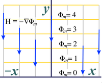 |
| Fig. 20a. Starting electric potential (shown with associated electric fields, red vectors) in the case of horizontal electric fields. | Fig. 20b. Starting electric potential (shown with associated electric fields, red vectors) in the case of vertical electric fields. | Fig. 20c. Starting magnetic potential (shown with associated magnetic intensity, blue vectors) in the case of horizontal magnetic fields. | Fig. 20d. Starting magnetic potential (shown with associated magnetic intensity, blue vectors) in the case of vertical magnetic fields. |
A case of matching potentials at the boundaries
The above starting fields are warped using one (or more) analytic functions as was done in the case of fluid flow in the earlier postings. A person decides among the various possible analytic functions by matching up boundary conditions to the potentials at the boundaries that the various functions provide.
Generally speaking, most situations have both Neumann boundaries and Dirichlet boundaries. In Neumann boundaries the vector field (fluid velocities in the fluid case) parallel the boundary walls and the potential lines are perpendicular to these boundaries. In Dirichlet boundaries, the boundaries run perpendicular to the vector fields and parallel to the potential lines. Dirichlet boundaries can be thought of as the sources of the fluid and electric fields: the fluid sources and sink in the fluid case, or the charges in the electric case. The Neumann boundaries serve to direct the vector fields, such as impermeable walls in the fluid case. Oddly, Neumann boundaries can be the sources in the magnetic case.

|
| Fig. 21. In fluid flow, nearly perfect Neumann boundaries are formed by any solid wall. Dirichlet boundaries are often only known approximately. |
Boundary conditions in fluid flow cases
The aspect of electric and magnetic fields that is different than that for fluid fields is these boundary conditions. In fluid fields, a Neumann boundary condition is a common occurrence. Any solid surface will prevent flow into itself and create an almost perfect Neumann boundary condition.
On the other hand, a perfect Dirichlet boundary, i.e. a set velocity potential at a boundary, is often difficult to precisely quantify in the case of fluid flow. Thus, in fluid flow, we usually start with the Neumann boundaries because they are well known and then we look for a "reasonable" approximate match with the Dirichlet boundaries.

Boundary conditions in electric fields

| 
|
| Fig. 22a. In the electric field case, nearly perfect Dirichlet boundaries occur at all metal surfaces. Neumann boundaries are often only approximately known. | Fig. 22b. Dielectrics (glass, ceramic, plastic) with large dielectric constants tend to channel electric fields. These materials can be used to create Neumann boundaries. Be warned that these Neumann boundaries are usually far from ideal. |
In terms of which type boundary is known and which is only approximately know, the electric field case is usually exactly opposite that of the fluid case. In electric fields a Dirichlet boundary is a common occurrence, since any metal plate will have a constant electric potential across its surface and thereby create such a boundary.
On the other hand, a perfect Neumann boundary is difficult to precisely quantify. Perhaps the closest we get to a Neumann boundary is when the electric fields run inside a long dielectric with a large dielectric constant. In this case the electric fields will run fairly parallel to the surface, having potential lines perpendicular to the surface and thereby make a reasonable approximation to a Neumann boundary.
Sampling of electric field mappings
The following are electric field mappings made using the four analytic functions discussed in the previous postings.
 | 
| 
|
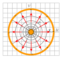
| Fig. 23a. This shows the electric field between two metal plates that are set at an angle with respect to each other. It uses a portion of the domain of the exp(z), i.e. ez, analytic function operating on the electric potential of Fig. 20b. It is similar to the mappings shown in Figures 8a and 8b. | Fig. 23b. This figure shows the electric field between two concentric metal tubes, the inner one positively charged and the outer one negatively charged. The function exp(z) is applied to the field shown in Fig. 20a with the vector direction reversed (also invert the sign of the potentials). It is similar to the mapping in Fig. 9a.
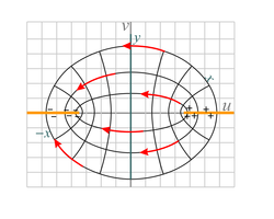
This geometry and fields are those found in typical coaxial cable. | Fig. 23c. Shown is the electric field between two oppositely-charged, spaced metal sheets. We see the end view of the metal sheets (shown in orange). They are separated by distance 2. The function sinz is applied to the field of Fig. 20a. This is similar to the fluid flow mapping shown in Fig. 10a. |
| 
|  |
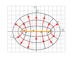
| Fig. 23d. We see the electric field from a metal strip of width 2. We see the end view of the strip which is shown in orange. The function sinz is applied to the negative of the field of Fig. 20b with the domain of that original field being restricted to −&pi/2 ≤ x ≤ 3π/2 and y ≥ 0 . This is similar to the flow mapping shown in Fig. 10d with a change in domain. | Fig. 23e. This shows the electric field above a large charged conductor located with its surface along the x-axis. The conductor has a deep groove cut in it. We see the end view in this figure. This mapping is made with the analytic fuction z + 1/z applied to Fig. 20b. The electric fields extend to the left and right beyond those shown. The fields inside the groove are very weak. This is similar to the mapping shown in Fig. 11b. |

| 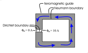
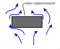
|
| Fig. 24a. Type I superconductors (and type II under many conditions) act as almost perfect diamagnets, totally excluding magnetic fields from their interiors. The surfaces of these superconductors form nearly perfect Neumann boundaries for the space outside the superconductor. This figures does not address the outer boundaries of this outside space. | Fig. 24b. "Soft" magnetic materials (i.e. ferromagnetic material such as iron) channel magnetic fields. This effect is commonly used in the magnetic guides (magnetic circuits) in electric motors and transformers as shown here. Not shown are the coils of wire wound around the guide to produce the magnetic field shown. The surfaces of the guide (for which the magnetic field is parallel) form Neumann boundaries for the space inside the ferromagnetic material. The channeling is not perfect and the Neumann boundaries are only approximate. |
Boundary conditions in magnetic fields
In magnetic fields, a type I superconductor will act as a nearly perfectly diamagnet, repelling all magnetic fields outside itself, and will force those magnetic fields to run parallel to its surface and have their magnetic potentials perfectly perpendicular to the surface. Also, magnetic fields inside a long piece of magnetic material will run fairly parallel to the surface and create an approximate Neumann boundary condition. Creation of a Dirichlet boundary is more difficult.
Sampling of magnetic field mappings

| 
| 
|
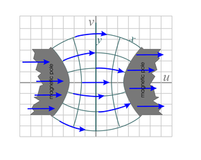
| Fig. 25a. Mapping of magnetic field, H, above an iron pole piece of a large magnet. The vectors inside the pole piece are exaggerated in magnitude and only in the approximate direction. This mapping uses the analytic function z0.8 over the domain −∞ < x < ∞ and y > 0 . We start with the inverse of the function shown in Fig. 20d (multiply all potentials by a minus sign and reverse the direction of the magnetic fields shown). | Fig. 25b. This is the magnetic field around a long conductor carrying electrical current (in a direction coming out of the page). It is a mapping of the inverse of the field in Fig. 20d. The mapping function is ez applied over the domain x > a and 0 ≤ y ≤2π, where a is the radius of the conductor. There is a discontinuity in the mapped potential at the point where the polar angle φ goes from 2π to 0 in the counterclockwise direction, but because the gradient of this potential is independent of φ we can just assume the gradient (i.e. H) remains constant through this step change in Φ. | Fig. 25c. The magnetic field between two curved iron pole pieces that make up a larger magnet. This is a mapping of the inverse of the function shown in Fig. 20c, mapped with the analytic function sinz over the domain −a < x < a and −∞ < y < ∞ , where 0 < a < π/2 . It is similar to the mappings in Figures 10a and 23c. |
|  | |
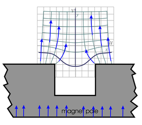
| Fig. 25d. This figure shows the magnetic field above an iron pole piece that has a long slot milled in it. The magnetic field inside the pole piece is very approximate. The field in the air is a mapping of the inverse of the magnetic field of Fig. 20d. It is mapped with the analytic function z + 1/z over the domain −∞ < x < ∞ and y ≥ 0 . It is similar to the fields shown in Figures 11b and 23e. | ||
Laplace's equation as applied to resistive flow of charge and fluid.
Another area of technology that uses Laplace's equation is the resistive flow of electrical current or of fluids. In the electrical case, this means the constant flow of currents inside a two or three dimensional solid of constant conductivity, σ. In fact researchers have long used this fact to arrive at experimental solutions of Laplace's equations by constructing the appropriate geometry on conductive paper called teledeltos paper or in electrolytic tanks full of an electrically conductive saltwater solution. Use of teledeltos paper and electrolytic tanks allow experimental measuring of potentials in a space with the desired boundaries to simulate the boundaries and solutions to Laplace's equation for technological problems, such as the flow of air over wings, water through turbine blades or relevant to various electromagnetic devices.For those knowledgeable in electromagnetic fields, we can derive Laplace's equation for resistive flow in the static electric case as follows. For static fields we cannot have a continuing build up of charge, i.e. in the long-term the charge that flows into a region must balance that flowing out. Therefore the divergence of the current density, J, must be zero throughout the region of interest: ∇⋅J = 0 . In a conductive solid the current density flow in response to the electric field is J = σE , where σ is the conductivity (assumed constant) and E is the electric field. The potential is defined such that E = −∇Φ . Putting these equations together gives Laplace's equation: ∇⋅J = ∇⋅σE = −σ∇⋅∇Φ = ∇2Φ = 0 .
A similar resistive flow, also controlled by Laplace's equation, occurs in fluids where the fluid layer is thin and the dominant force is viscous friction between the fluid and the solid bottom (and perhaps also a top in the case of fluid flow between two plates). While the fluid velocity will vary with distance from the solid, we can instead consider only the velocity averaged over the fluid depth. In general, this average velocity will vary from location to location and much like the above electrical counterpart, will obey Laplace's equation: ∇2Φv = 0 , where Φv is the velocity potential and is related to the average velocity by vav(x,y) = −∇Φv .
Laplace's equation as applied to time varying electric and magnetic fields
Depending on the frequency, time varying or AC magnetic fields are often excluded from metals. Technically AC fields obey the Helmholtz equation and not Laplace's equation. However if the dimensions of the area of interest are small compared to a wavelength of electromagnetic radiation then these fields approximately obey Laplace's equation. Thus, in these situations we can use conformal mapping to calculate the magnetic fields and the metal edges form Neumann boundaries. The electric fields can also be so modeled and the metal edges form Dirichlet boundaries as in the static case. Typical applications might include modeling the fields around a small detail such as a tuner or coupling port in a microwave resonator, or modeling the fields around an antenna that is much smaller than the wavelength it is broadcasting or receiving.

Copyright, P. Ceperley, September 2010
| Other postings by author | last: Conformal mapping 3 | up: Conformal mapping contents | next: Detailed mappings |