| Other postings by author | back: Conformal Mapping 2 | up: Conformal mapping contents | next: Conformal Mapping 4 |
In the previous posting we discussed some of the fluid flow patterns addressable with the complex function w = zn. There are many other possible analytic functions which could be applied to fluid flow. In this section we will explore three of them:
- w = ez,
- w = sin z, and
- w = z + 1/z .
 |  |
| Fig. 8a. Flow pattern for vortex flow in the case where there is no rotation in the parcels of fluid even though there is net circulation around the origin. This is an approximation of many vortex flows in nature.
Shown is the conformal mapping using the mapping function w = ez applied to the velocity potential function Φ = −Ay, where the xy-space is restricted to values in the range x ≥ a > 0 and 0 ≤ y ≤ 2π . A is positive. There is a discontinuity as we pass counterclockwise between the polar angle φ = 2π and φ = 0. The uv grid is shown not drawn to scale. See the more detailed mapping in Fig. 26c of a future posting for a more accurate grid. To do this mapping by equations we need y as a function of u and v. We expand our mapping function: w = ez = ex+iy = ex⋅eiy .
| Fig. 8b. The conformal mapping using w = ez of the xy-space for y being restricted to 0 ≤ y ≤ π . This would correspond to the fluid flow resulting from a wall positioned at v = 0 , a linear source of fluid being placed along the positive u-axis (just upwards from the wall) and a linear fluid sink along the negative u-axis.
This figure shows the angle subtended by the flow equal to 180 degrees. By choosing different ranges for y we could make flow patterns with other angles. |
| Here we calculate the velocity field for the flow presented in Fig. 8a for which Φ = −Aφ .
Taking the gradient, we get: Applied to our potential, we have That is, the flow is in the positive φ direction and is inversely proportional to the radius, i.e. the fluid swirls faster as you get nearer the origin. Since the velocity is constant with respect to φ, we can ignore the discontinuity in Φ and just assume the velocity also remains constant crossing from φ = 2π to φ = 0. |
The function w = ez
This function warps a rectilinear grid into a polar grid (with the circular grid lines having unusual spacing, i.e. their spacing being proportional to the radius.)
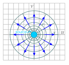
- The function w = ez maps the originally horizontal flow into vortex flow around the origin as shown in Figs. 8a and 8b.
- It maps originally vertical flow into radial flow as shown in Fig. 9.

| 
| 
| 
|
| Fig. 9a. Flow pattern for radial flow away from a circularly symmetric source of fluid.
The mapping function w = ez is applied to the velocity potential Φ = −Ax, where the xy-space is restricted to the range x ≥ a > 0 and 0 ≤ y ≤ 2π . A is a positive number. In the caption for Fig. 8a, we derived the relation for this mapping function r = ex which can be inverted to give x = lnr. Substituting into our velocity potential gives: Φ = −Ax = −A lnr . | Fig. 9b. The flow pattern for radial flow towards a circularly symmetric sink of fluid located at the origin. In terms of our conformal mapping this corresponds to a positive sign before the A value in the velocity potential function discussed in the caption for Fig. 9a, i.e.
Φ = Ax. This results in a mapped velocity potential of
Φ = A lnr.
The equation for the velocity is v=−∇Φ=−∂Φ/∂r ar − r−1∂Φ/∂φ aφ . Applied to our equation for Φ this gives v = −1/r ar which indicates that the flow velocity is in the negative radial direction (towards the origin) and proportional to 1/r, i.e. faster towards the center. | Fig. 9c. The same mapping as Figure 9a except that the original xy space is restricted to 0 ≤ y ≤ π .
This corresponds to a source emitting fluid next to a wall (shown as a horizontal black line). |
The function w = sin z
Below are various fluid flow patterns solvable by this complex function. One method of calculating the sine function for complex arguments is by using ez:
sin z = (eiz − e−iz)/2i .
 |  | 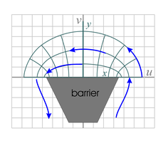 |
| Fig. 10a. This shows the mapping resulting from applying w = sin z to the potential for horizontal flow, Φ = Ax, where the xy-space is restricted to −π/2
≤ x ≤ &pi/2 and there are no limits on y.
This corresponds to a linear fluid source and linear fluid sink positioned as shown, along the x-axis with a gap between them. If no scaling factors are used, the gap has a length of 2 units. See the more detailed mapping of sin z. | Fig. 10b. This is basically the same flow equation as in Fig. 10a, except that the xy-space is restricted to 0 ≤ x ≤ &pi and y is restricted to positive values.
See the more detailed mapping of the flow pattern. The physical setup involves a barrier along the x-axis up to x = π/2 and a source and sink of fluid along the y-axis as shown. | Fig. 10c. This is basically the same flow pattern as in Fig. 10a, except that the xy-space is restricted to &pi/2 ≤ x ≤ &pi/2 (as in Fig. 10a) and y is restricted to positive values.
The physical setup involves a barrier along the u-axis between u = −1 to u = 1. There are sources and sinks of fluid along the u-axis as shown. |
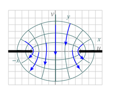 | 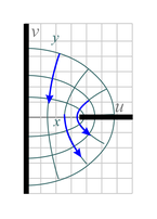 |  |
| Fig. 10d. Here we have mapped the initially vertical flow instead of the horizontal flow used in Fig. 10a (Φ = Ay). The xy-space is restricted to that of Fig. 10a.
The physical setup involves fluid flowing through a 2D hole (corresponding to a slot in 3D) from the upper half space to the lower half space. | Fig. 10e. This is similar to Fig. 10d except the xy-space is restricted to 0 ≤ x ≤ π/2 and y is not restricted. |
The function w = z + 1/z
 | 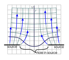 |  |
| Fig. 11a. This illustrates an initially horizontal flow (Φ = Ax) as mapped by the function w = z + 1/z . The range of x is not restricted, while y is limited to positive values.
The physical setup involves a 2D hole (a slot in 3D space) and walls as shown (walls for x ≥ 1 and x ≤ −1 ). The hole is dead-ended, preventing fluid from escaping through any of the lower half surface boundaries. In reality, the hole cavity simply would need to be large compared to the slot width. | Fig. 11b. The above is similar to Fig. 11a, except that we start with initially vertical flow (Φ = −Ay ). See the more detailed mapping of this function. The physical setup involves a line source where the wall was in Fig. 11a, with the same dead-ended hole in the middle. |
Copyright, P. Ceperley, September 2010
| Other postings by author | back: Conformal Mapping 2 | up: Conformal mapping contents | next: Conformal Mapping 4 |