| All postings by author | previous: 3.13 Coupling strength | up: Contents | next: 3.15 Resonant scattering of waves - 1D |
This posting includes flash animations showing the physics discussed. Most computers have a flash player already installed, but if yours does not, download the free Adobe flash player here.
|
3.14 Waveguide excited resonator with circulator
Summary: The animation in this posting shows a resonator excited by waves on a waveguide. A circulator is used to separate the positive-going from the negative-going waves in the waveguide to make it easier to study the negative-going waves. These negative-going waves contain information about the resonator and the coupling to the waveguide.
Keywords: resonator, cavity, waveguide, transmission line, circulator, flash animation
Topics covered in this posting
- An animation which depicts the interaction of waves in an acoustic circuit and a resonator is presented and discussed.
- A circulator, a device common in microwave circuits, is included to more clearly separate the incident and negatively-going waves.
Contents of this posting
1. Description of animation

Below we have an animation similar to the one in posting 3.12 with the major differences being that:
- The waves are acoustic instead of mechanical (waves on a string) and
- We use a circulator (explained below) to separate the incident wave from the negative-going wave
A more detailed description:
- As with the last animation, mouse over the animation to see the action, mouse off it to suspend the action and click on it to restart it. Suspending the animation by mousing off the animation will not suspend the sound.
- Pipes serve as acoustical waveguides.
- The waves which consist of acoustical pressure peaks and valleys are shown as red and blue color shading inside the pipes.
- There is a circulator which separates out the incident waves from the negative-going waves. This functions similar to circulators used in microwave circuits.
- The resonator is a half wavelength long closed pipe section with a small hole joining it to the nearest waveguide/pipe. The resonator is somewhat exaggerated in length to make it visually clearer.
- The graphs just above and below the waveguides plot the acoustical pressure versus position along the waveguides. These graphs change as the waves progress. The graph for the acoustical pressure inside the resonator is rotated 90 degrees because the resonator is tipped up from the orientation of the adjacent waveguide. (It could optionally be in line with the waveguide if desired.)
- The acoustical waves as sensed by three microphones are plotted versus time in the lower "oscilloscope" graphs.
- The coupling is initially set at unity coupling (β = 1) but can be changed by clicking on the buttons in the lower left hand corner. After clicking on a button, mouse off the button (but still over the animation) to see the action. The resonator is coupled to the waves in the waveguide via a small hole that connects the two. The coupling strength is controlled by the diameter of the hole.
- The sound can be toggled off and on by clicking on the button at the top right of the animation. The animation must be restarted (by clicking on the animation) after the sound is restored to hear sound again.
2. The animation - acoustical waveguide excitation of resonator with circulator
| Fig. 35. See the paragraph just above for a description of the animation. |
3.Discussion of animation
- As with the earlier animation, a short sinusoidal burst of waves is launched down the waveguide towards the resonator. These waves are called the "incident" waves.
- The incident waves propagate to the resonator where they excite the resonator.
- The interaction of resonator and adjacent waveguide can be described as
- Initially in most cases, most of the incident waves reflect off the entrance of the resonator. We called these initially reflected waves the "simply" reflected waves.
- As the resonator becomes excited, it radiates additional waves down the attached waveguide.
- If the incident wave's frequency matches the resonant frequency of the resonator, the simply reflected wave and radiated wave are phased to partially or totally cancel each other, depending on the coupling strength of the resonator to the waveguide.
- At "undercoupling" (β < 1), the radiated wave is smaller in amplitude than the simply reflected wave and so only partially cancels the reflected wave. The total negatively propagating wave is smaller than the incident wave, meaning that some of the power of the incident wave is absorbed by the resonator.
- At "unity coupling" (β = 1), the radiated wave equals the simply reflected wave in magnitude and completely cancels the simply reflected wave so that the amplitude of the negative-going wave is zero. In this state, the resonator absorbs all the power of the incident wave. This power is absorbed by the internal losses of the resonator itself. At this coupling strength, the amplitude of the wave field inside the resonator is the largest possible with the given power of the incident wave and a given resonator Q0, consistent with the graph in Fig. 31 of the previous posting.
- With "overcoupling" (β > 1), the radiated wave is larger in amplitude that the incident wave and more than cancels the reflected wave, actually creating a total negative going wave that is opposite in sign (180 degrees phase shift) from what the simply reflected wave. Thus, the negative going wave is not zero in amplitude, and carries appreciable power away from the resonator.
With overcoupling (a larger coupling hole), the incident wave is more strongly coupled to the internal wave field of the resonator, but the larger hole, also means that more of the resonator's internal waves are radiated back out through the coupling hole. This results is less of a build up of waves inside the resonator than was the case at unity coupling and a lowering of its loaded Q, QL. - With overcoupling, a lot of the incident wave amplitude washes through the resonator, making the resonator less independent and less able to recycle its energy and more like an extension of the waveguide. Consistent with this lower independence, the resonator will have a broader bandwidth, meaning that a wider range of frequencies will excite it.
- The last effect, that of overcoupling, results in lower resonator excitation (compared with the unity coupling case). This effect has parallels in the act of pushing a child on a swing. Most people pushing a child on a swing realize that it is best not to become too tightly coupled to the swing, but to give short impulses to the swing once for each cycle. Longer pushes (stronger coupling) often slow the swing down.

4. Superposition of waves versus conservation of energy
The above discussion uses two important principles:
- Superposition of waves and
- Conservation of power and energy.
Most simple waves are at least approximately linear when described in terms of the normal oscillating parameters, such as acoustic pressure, string deflection, electric field strength, etc. Being linear allows us to break a wave up into components such that the sum of oscillating parameters of the components equal that of the total observed wave. For example, in the case of acoustical waves, the sum of the oscillating pressures of the component waves will equal the oscillating pressure of the total observed wave. In the animation above, we describe the negative-going wave in terms of two component waves: the simply reflected wave and the radiated wave. Each of these components are clearly attributed to a specific source: the simply reflected to the incident waves and the radiated to the oscillations inside the resonator.
No simple conservation law applies to these component waves, except that their total must add up to the observed wave which does have conservation laws by itself. Usually we pick the component waves that help our understanding of the physical process, for example by breaking the negative-going wave into the simply reflected and the radiated waves, neither of which are separately observable. We can do this even in the extreme case where the total observable wave is zero, such as in the unity coupling case above. In that, the observable negative-going wave is zero, yet we can treat it as being the superposition (i.e. sum) of two non-zero component waves (the simply reflected and the radiated waves) which cancel each other.
We need to resist the false assumption that the power (or energy) in the component waves adds to equal the power (or energy) in the observed waves. When we are dealing with power and energy of waves, we often need stick to the observed (or observable) waves only. Going back to the two components of the negative-going wave in the unity coupling case, the power of each component (if we falsely calculated it) would certainly not be zero. Then because power is always positive the sum of the powers of the components would not be zero. This is in conflict with the fact that the two wave components cancel each other resulting in a zero total wave which would have zero power. This confirms the fact that power and energy are not linear and thus we must avoid discussing power and energy of unobservable component waves. We cannot break a wave into components for the sake of calculating power and energy, unless the components are separable in a physical setup. Even for separable interfering waves, the details of power and energy flow are quite complicated, much more so than the linear oscillating parameters such as acoustic pressure, etc.
5.Absorption of power from waves via emission of a canceling wave

The above animation illustrates the concept that resonators absorb energy from a wave by radiating a second wave that cancels some or all of the incident wave. The resonators radiate a canceling wave as a means for absorbing energy from the incident wave. In the above animation, the canceling wave is called the "radiated wave" and totally or partially cancels (depending on the coupling) the simply reflected wave, thereby reducing the power in the negative-going wave. This missing (or canceled) power ends up inside the resonator as additional stored energy and in the internal losses of the resonator.
6. Math for resonant scattering with a circulator
Below is a summary of equations appropriate for the above simulation. These equations were taken from the previous posting.
| Summary of results of scattering using a circulator from posting 3.13 (with the acoustical pressure amplitude p replacing the vertical force transmitted by the wave on a string, as appropriate when changing to an acoustical system.) |
|---|
Definition of coupling coefficient, β, and relation of β to incident and radiated waves. Lower case p is the acoustical pressure (the oscillating pressure in sound) while upper case P is the power in the wave:
 (170a)
|
Relation of incident and radiated waves to coupling coefficient:
 and
and
 (170b)
|
Relation of scattered (negative-going) wave and incident wave to coupling coefficient:
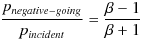 (170c)
|
Relation of resonator energy to various parameters:
 (170d)
|
Relation of fractional bandwidth to coupling coefficient and Q0:
 (170e)
|

| All postings by author | previous: 3.13 Coupling strength | up: Contents | next: 3.15 Resonant scattering of waves - 1D |