| Other postings by author | back: Conformal Mapping 1 | up: Conformal mapping contents | next: Fluid flow patterns handled by other functions. |

|
| Fig. 1. Screen shot of the animation from the previous posting, i.e. Fig. 1 of that posting. |
Conformal mapping II
In the previous posting, we introduced conformal mapping. These are mappings made on the complex plane by complex analytic functions. A huge use of conformal mappings in technology is their use in solving Laplace's equation, which is the defining equation for many fluid flow situations. Conformal mappings allow us to transform (i.e., morph) one known solution to Laplace's equation into another solution.
In this posting we continue to explain the concepts of conformal mapping and their applications in fluid flow.
More on analytic functions
Analytic functions are complex functions that obey the Cauchy-Riemann equations.
where u and v are the real and imaginary parts of the function, i.e. f(z) = u + iv. Also x and y are the real and imaginary parts of the independent variable: z = x + iy.
These equations are derived from the assumption that the complex function, f(z) should have the same derivative df/dz no matter which direction in the complex plane dz is oriented. After all, if we forget for a moment that z is complex and take the simple-minded derivative, i.e. pretending f and z are real, we get one answer. For example, for the function w = zn we would like to use the rule for differentiating xn, that is dxn/dx = nxn−1. Then we could write: dzn/dz = nzn−1.The derivation of the Cauchy-Riemann equations goes as follows. We start by writing the definition of the derivative two ways, one for letting dz be in the dx direction and one for in the dy direction:

 , (4.1)

 . (4.2)
|
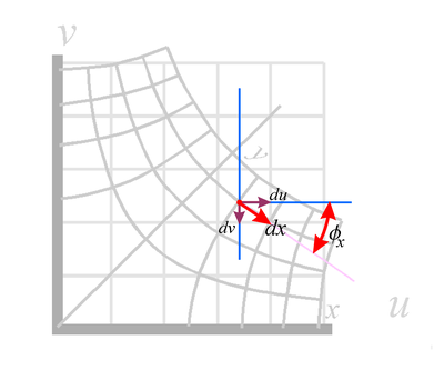
| Fig. 3a. Components of dz = dx. |

|
| Fig. 3b. Components of dz = idy. |
We next equate Equations (4.1) and (4.2). This means equating their real parts, which gives Equation (3a) and their imaginary parts, which gives Equation (3b) ).
Graphical interpretation of the Cauchy-Riemann equations
We see the concept of taking the derivate in the dx direction and then in the dy direction illustrated at the right, in Fig. 3. In this figure we show the function w = z½ (as a typical complex function... we could have picked any analytic function) transforming the z = x + iy complex space into a w = u + iv space as discussed above. We can view Fig. 3a. as a transform or just as a nice way to view the complex function.
To view this as simply the function, we start by finding the x,y coordinates of the point we are interested in on the warped x-y grid. We then read off the value of the function, i.e. its u,v values, on the non-warped u-v coordinate grid.
Shown in red is a dx vector at some arbitrary point. Note that it is parallel to the warped x-axis at this point, as it should be. We also show its du and dv components and the angle φ that dx makes with the u (or horizontal or real) axis. φ is an angle not a velocity potential. In the case shown, dv is negative, since dv point in a downward direction.
We know from simple trigonometry (see vector components or vector projections) that:
du = adx cosφx which means that ∂u/∂x = a cosφx (5.1) ,
where a is a scaling factor for dx (assuming that the warped grid is stretched or compressed in the warping process). a will most likely vary from point to point, but we consider it at one specific point for the moment.
Similarly:
dv = −adx sinφx or ∂v/∂x = −a sinφx . (5.2)
Figure 3b shows the case where dz = idy. The component equations are (with b as the scaling factor in the dy direction):
du = bdy sinφy or ∂u/∂y = b sinφy , (5.3)
and
dv = bdy cosφy or ∂v/∂y = b cosφy (5.4) .
Substituting the values of partial derivatives from Equations (5.1) to (5.4) into the Cauchy-Riemann equations above (Equations (3.1) and (3.2) ) we see that:
a sinφx = b sinφy , (5.5)
and
a cosφx = b cosφy . (5.6)
Dividing one equation by the other, we get:
tanφx = tanφy
, (5.7)
Substituting Equation (5.8) into Equation (5.5) shows that a = b . (5.9)
Thus we see that while analytic functions warp and distort a grid, the Cauchy-Riemann equations imply:
- the warped x and y grids are perpendicular to each other at all points of intersection (they maintain orthonormality), and
- the scaling (i.e. shrinking or expanding) of the x grids the same amount as of the y grids. Thus small grid squares are mapped to small grid squares and not to rectangles.
You can see both these effects in the warped grids of Fig. 3.
Comparison of complex derivatives with derivatives in a normal two dimensional space.
How do derivatives of analytic function in the two dimensional complex plane compare with derivatives in a two dimensional vector space?
ANSWER: In science and technology we deal with many vector fields, many of which do NOT obey Laplace's equation. These include flow of fluids where viscosity is important and there is rotation (swirling) of the fluid, and also electromagnetic fields having charges and currents in the space of interest.
In the study of general vector fields we commonly use several types of derivatives. These include:
- the gradient,
- the divergence, and
- the curl.

The requirement that complex analytic function have direction independent derivatives leads to these functions being restricted to functions that obey Laplace's equation. What makes analytic functions so interesting is that most simple functions that a person might innocently write down as a function of z are analytic and do obey Laplace's equation. They therefore are of great interest in the study of physical systems that obey Laplace's equation.
2D versus 3D space using conformal mapping
Conformal mapping is great for two dimensional problems. This is due to the fact that the complex plan (i.e. the complex space) is intrinsically a two dimensional space. Thus a method, such as conformal mapping, that relies on complex functions are well matched for work in a two dimensional space. While people have worked to extend this method to three dimensions the result is not nearly so elegant or useful as the standard two dimensional conformal mapping.
We live in a three dimensional universe, however there are a lot of physics and engineering problems that are mathematically two dimensional (2D). These are problems are problems in which the third dimension is mathematically unimportant or mathematically trivial. This means that the sources of fields and constraints to the fields are constant in the third dimension, or can be approximated as such. Typical examples of two dimensional problems are:
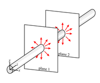
- The electric field around a very long straight wire (Fig. 4a). If we let the z-axis be in the direction of the wire, then we expect nothing to change in the z direction as long as we are somewhere in the middle of the wire, away from its ends. We expect the fields in a 2D slice to be about the same no matter where the slice is made, as long as we avoid the ends. In the 3D version of Laplace's equation,
 , the last term is zero because Φ does not vary with z thereby allowing us to ignore the z coordinate.
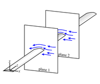
- The fluid flow field around a very long uniform wing (or turbine blade, etc ... Fig. 4b), again as long as we stay away from the ends of the wing.
- The flow in a shallow container of water (Fig. 4c) having a flat bottom, if the viscosity of water is not important for the flow. We also need any objects of constraints to the flow to be constant in the vertical direction. This would also apply to fluid constrained between to flat plates, with vains in the region that are constant in shape in the direction perpendicular to the plates.
- The magnetic field in the region of two pole pieces (Fig. 4d) that are uniform in the z-direction and much longer in that direction that the space between the pole pieces.
Conformal mapping is also often used in problems that are more accurately done using a 3D method, just to get a rough approximation to the field shape and approximate values.
|
|

|

|
| Fig. 4a. | Fig. 4b. | Fig. 4c. | Fig. 4d. |

|

|
|

|
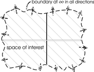
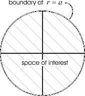
| Fig. 4e. Boundaries of whole space. | Fig. 4f. Boundaries up upper half space. | Fig. 4g. Boundaries for a circular space with the boundary at a fixed radius. | Fig. 4h. Boundary for a rectangular space. |
More on Laplace's equation: boundary conditions and the uniqueness theorem
This is perhaps a good point to discuss boundary conditions and the uniqueness theorem of Laplace's equation.
In the solving of Laplace's equation, a person needs to define the space over which the solution is to exist. Is it the whole universe? Or is it the upper half space, with y > 0? Or some smaller region? The "boundary" is the edge of this space, i.e. a magical mathematical container that sets the edge of the space of interest. This boundary may be at infinity, or partly at infinity (as in the case of using a half-space), or might be all finite (such as a box or a cylinder).
Solving Laplace's equation means getting the values of the field of interest (such as the velocity potential) at all points in our space. The "value" might mean an equation for the value as a function of position or a huge array of numerical values of the field for all sorts of points, as is obtained in a computational solution.
In order to solve Laplace's equation we need to know something significant about the field at all points along the boundary. Usually, the thing that we are given at the boundaries are either the values or the direction of the gradient (derivative) there. Known values of the function at a boundary is called a Dirichlet boundary condition, while known derivative is called Neumann boundary conditions. Usually we know the values at some of the sides of a particular space and the derivatives at other sides of the space.
For Laplace's equation, once the values of the field is set along the boundary, the values of the field at all points inside the boundary are determined or fixed (but unknown as yet). We can rest assured that there is one and only one solution to Laplace's equation for a given set of boundary conditions for the space of interest. The uniqueness theorem is a formal statement of this and is proven in many texts and online sources.
The job of solving Laplace's equation involves figuring out what the "determined" interior values are starting from the boundary values or conditions. It is a mathematical puzzle to be cracked. There are a number of ways to solve Laplace's equation. Conformal mapping is one of these methods.
One advantage of using conformal mapping is that it can be very graphical. Once a person figures out what to look for, finding the solution can boil down to looking through a number of conformal transforms or mappings and finding one that visually matches the boundaries at hand. It is perhaps the least mathematical of the solution methods.

|
|

|
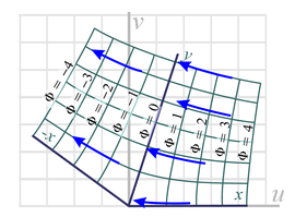
| Fig. 5a. Starting knowledge of boundary and rough flow pattern. | Fig. 5b. Possible conformal mapping to fit the rough flow pattern and boundary. The analytic function used is w = z0.8. |
Examples of picking an analytic function suitable for a particular fluid flow problem.
For example, suppose we want to examine fluid flow along a rigid wall that has a sharp bend in it as shown in Fig. 5a. Here the boundary conditions are that the flow should be uniform well away from the bend, and the flow should follow the wall in regions immediately next to the wall. In terms of flow potential, this means that the potential lines should be perpendicular to the wall at all points and are a little nebulous on the other boundaries. We need to search for an analytic function that primarily matches the lower boundary condition and is reasonable on the other boundaries. The boundary condition, that of the sharply bent wall, strongly suggests the function we have discussed at some length above, i.e. w = zn.
Adjusting the power n in the function (Equation 5.10) to get the same bend gives us the mapping shown in Fig. 5.b. We choose the wall to lie along the x-axis and the lines of constant velocity potential (the equipotential lines) lie along the grid lines of constant x values.
Now we check all the boundary conditions in this mapping to see if they are what we want.
- At the lower boundary, the velocity potential lines should be everywhere perpendicular to the lower edge of the space and indeed they are because the chosen grid lines (lines of constant x) are perpendicular to the x-axis (representing the wall) because of the orthonormality property discussed above. Thus our choice meets the lower boundary condition requirements. Note also that the lines of constant y values are perpendicular to the equipotential lines and therefore show the direction of the velocity vectors. We call such lines streamlines.
- The top of our space is really at y = ∞ and there we would like the flow to roughly mimic the flow on the lower boundary. It does, so this boundary is ok.
- On the right and left edges we would like the flow to enter and leave in a smooth fashion, roughly perpendicular to the entrance and exit. It does, so this boundary condition is satisfied also
- Since this "solution" to Laplace's equation meets out boundary conditions, it must be "the solution" to Laplace's equation we are seeking (since the uniqueness theorem says there is only one solution for a given boundary condition).
- Note that we could have used this solution for any problem that has boundary conditions consistent with this solutions, i.e. rigid walls along any of the grid lines of the solution. Figures 6a and 6b show other possible boundary conditions and choices of space that are consistent with this solution.
- Another way to use the above conformal mapping (w = zn) is to start with an initial simple solution that has the velocity potential vary with y, i.e. vertical flow in the initial xy-space. In this case the lines of constant y are the equipotential lines and the lines of constant x are the streamlines. In this case the fluid is coming from above (from infinity or from a fluid source depending of the figure) and flowing downward into a fluid "sink" at the lower boundary. Now the initial non-distorted solution of Laplace's equation is Φ = y (instead of Φ = x as we used before). These solutions are just as valid as a previous horizontal flow solution and the mappings of them are also equally valid, as long as we can match the new boundary conditions. We show this solution matched to a few boundary conditions below in Fig. 7.
- The actual velocity vectors are given by the gradient of the velocity potential. The magnitude of the velocity at any point is inversely proportional to the distance between adjacent equipotential lines.
- A reader may wonder why we mess with the velocity potential and do not simply map the velocity field with our analytic functions. The answer is that the velocity field does not obey Laplace's equation and our analytic functions do not map one velocity field into another correct velocity field. So to get correct results, we must do the mappings on the velocity potential and only after that convert the velocity potential into a velocity field which is usually more of interest than the velocity potential. The velocity field can be used to calculate such parameters as the force on the wall constraining the fluid to flow in a certain pattern and the viscous friction in the flow (assuming that the viscous forces are not so great as to make Laplace's equation not longer applicable to our flow.)
- In conclusion, from this example we can see that solving by conformal mapping of solving involves finding an analytic function that produces the right "shape" of warped grid lines as needed for the boundary conditions at hand, either in the whole space or in some subspace or part of the warped grid.
Copyright, P. Ceperley, September 2010.
| Other postings by author | back: Conformal Mapping 1 | up: Conformal mapping contents | next: Fluid flow patterns handled by other functions. |


