| up: home | next: part 2 |
| Contents |
|---|
In this posting we take the reader through the workings of mechanical clocks. These include pendulum, balance wheel, and quartz clocks (those that have gears inside and analog clock hands outside). The common element in all of these is their use of gears. Gears provide for the precise translation of ticks of a pendulum (or balance wheel, etc) into revolutions of the hands on the clock face. We will proceed here to explain the working of these clocks by starting with their gears. P. Ceperley, Jan 2010
 |
|
Wikipedia Fig. 1. Meshing gears. |
1. Two meshing gears
Figure 1 shows two meshing gears in rotation. As they rotate they are locked together, tooth for tooth. However, because there are more teeth in the large gear than the small one, when the small one has turned one revolution and used all its teeth once, the large one has only used a fraction of its teeth and completed a fraction of a revolution. Because the small gear, as shown, has 10 teeth and the large gear has 28 teeth, the ratio of the angular speed (revolutions per minute or revolutions per second) is given by 28/10 = 2.8 . The small gear's angular speed is 2.8 times the large gear's angular speed.
In Figure 2 below, you can play around with turning the gears. Move your mouse around the rim of either gear to see the response of the other gear and observe how their motions are locked together. This animation works best if you move the gears somewhat slowly.
|
Mounting gears
Not shown in either Figure 1 or 2 is the method of supporting the gears. In Figures 3 and 4 we show two common ways of mounting gears on a frame and shaft, i.e. axle, so that their centers are fixed in space and they are allowed to turn. Note that the axles may be stationary (e.g. a pin stuck in a metal base with the gear free to rotate on the pin) or a shaft that is secured to the gear and rotates with it. There are many variations of these two mounting methods.

MorgueFiles |

MorgueFiles |

Public Domain - Wikipedia |
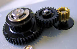
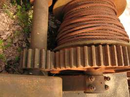
| Fig. 4a. Three gears (two plastic, one brass). The brass one is tight on its axle (connected to a motor, hidden from view), while the plastic ones are free to turn on pins (with circle clips holding them onto the pins). | Fig. 4b. Back of a modern clock showing its gears. These are mounted in a frame. Most gears shown in this figure have integral axles, whose ends can be seen protruding through the frame. | Fig. 4c. Old tower clock. This photo shows the large gears that were used and the method of supporting their shafts with strips of iron. |
Torque in gears
The torque (twisting force) passed on from one gear to another gear is changed by the ratio of their number of teeth. In Figure 5, the larger gear (which has 40 teeth) has four times the torque of the small gear which has 10 teeth. Geared devices like the winch in Fig. 3d use this feature to multiply the torque.
The reason for the change in torque is that torque on a gear is the product of force transmitted to the teeth times the average radius of the teeth (the distance from the center of the gear to the center of one tooth). In order to mesh properly, two meshing gears must have radii proportional to the number of their teeth. The gear with more teeth will have a proportionally larger radius. When two gears are meshing, the engaged teeth of one gear push with equal and opposite force compared with that of the engaged teeth of the other gear according to Newton's third law of motion. Thus, even though the forces at the teeth are the same for both gears, the larger radius of the larger gear means that gear has more torque transmitted through it.

|
| Aztec calendar |
| up: home | next: part 2 |


