| previous:part 1 | up: home | next:part3 - conclusion |
Understanding a mechanical clock - with animations - Part 2
| Fig. 6a. Various paired gears from a modern "quartz" clock. The gears drive the clock hands at the correct rotational speeds. At the bottom left is the tip of a small jeweler's screw driver (to give you a sense of scale). One gear has a through hole and is meant to turn freely on a fixed axle. Two gears have integral cast-in plastic axles. One gear has an integral metal axle. One gear is brass while the others are plastic. | Fig. 6b. The clock module whose gears are shown in Fig. 6a with its back removed to show part of the gear train in place. Following the white gears from top left to the right: the top gear is part of the motor (the magnetic part stuck to the screwdrive in Fig. 6a). This motor gear meshes with the next (beige) paired gear, which meshes then with next (white) gear. This next gear is also a paired gear with its smaller gear hidden below (see it inverted in Fig. 6a). The hidden small gear meshes with the large right-most white gear. The gear train continues at a lower level hidden from this view. |
2. Paired gears
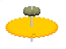
Clocks make extensive use of paired gears: two gears on the same axis that are bonded so that they turn together, as shown in various forms in Figures 6 and 7.
Figure 7c shows a paired gear meshing with two simple (spur) gears. We see that there are two sets of meshing gears in this case. If we drive gear 1 at one revolution per second, then gear 2 will turn at 1/4 this angular speed because it has four times as many teeth as does the gear 1. Because gear 3 is bonded to gear 2, it also turns at 1/4 revolutions per second. Gear 4 meshes with gear 3 and has three times the number of teeth as does gear 3 and thus turns at 1/3 the rotational speed of gears 2 and 3 and 1/12 the speed of gear 1. Since gear 1 revolves at 1 revolution per second, gear 4 must revolve at 1/12 revolution per second.
The point of this is that by using a paired gear set, we can get a multiplicative changing of the rotational speed at each gear stage. The ratio of rotational speeds of gear 4 of Fig. 7c to that of gear 1 is 1/4 x 1/3 = 1/12. That is, the ratio of the speed of gear 1 to the speed of gear 4 is the product of the ratios of the two sets of meshing gears (8:32=1/4 and 10:30=1/3). The assembly of all four gears is called a gear train. Gear trains form the functional backbone of all mechanical clocks. They allow for gearing ratios unattainable with a single pair of meshing gears.
Instead of merely viewing the gear train of Figure 7c, you can drag any one of the gears in the figure to control the speed yourself. Note that no matter which gear is driven, all turn together, tooth-to-tooth, in ratios of speeds defined by the ratio of the teeth of the meshing gears. Turning the left gear results in a very slow turning of the right gear (1/12th the speed), while turning of the right gear makes the left gear turn very fast (it may be a blur unless you turn the right gear slowly).

| Fig. 8a. Gear train of a pendulum clock. Mouse over the illustration to see the animation. The "delete escapement" button allows you to see the effect of deleting the pendulum and anchor escapement (which eliminates the escapement action). You can restore it by clicking the button again, or clicking "restore". The "faster" button allows you to see the action of the gears a little better by speeding up the pendulum. To speed it up more, click on "delete escapement". |
3. Gear trains in mechanical clocks
Figure 8a shows a gear train of a typical clock. As shown, it uses 3 paired gear sets plus the escape wheel (and its gear) and a separate hour hand gear. These gears convert a two-second-per-tooth speed at the pendulum to a one-revolution-per-hour speed at the minute hand gear, and to a one-revolution-per-12-hours speed at the hour hand gear. This gear train accurately translates the swings of the pendulum into revolutions of each hand of the clock.
Labeled on the figure are the number of teeth for each gear (those unlabeled small gears have 8 teeth each) and the gear ratio of the meshing gears. The minute and hour hands are shown on separate shafts to make the drawing easier to understand. (See below for the details of putting several hands on the same shaft.) This figure does not have the drag-it-yourself feature of the above animations because the total gear ratio is so extreme: turning the hour hand at a mere one revolution per 10 seconds, would make the far right gear turn at 2060 revolutions per second! Something that would be extremely hard to animate (or view!)
When we consider the friction in a real clock movement, the torque due to friction in the right hand gears would be multiplied by 20,600 if we tried to power the gear train from the left most gear. This would require more torque than the left hand gears could sustain without failing. Because of this, clock designers usually provide the driving force (i.e. weights or a wound up mainspring) to be applied to one of the central gears in the train. Such a location provides a reasonable tradeoff between torque and excessive play-out of the rope going to the weight.
Fig. 8a shows the workings of a typical pendulum clock, such as was traditionally found in foyers and on mantelpieces. These used a weight and pulley to turn the gears and power the clock (which needed to be rewound daily). The pendulum and escape wheel regulated the rotational speed of the gear train. The pendulums in these clocks typically had a period of 1 to 3 seconds, depending on their lengths. Details of this type of clock can be found in an earlier posting and in Wikipedia.

| Fig. 8b. Animation of a typical balance wheel escapement. Mouse over the figure to see the action. This escapement is used in wrist watches and pocket watches in place of the pendulum in Fig. 8a. |
In classic pocket watches and wrist watches, a balance wheel was used in place of the pendulum. Even though they are less accurate, balance wheels are much smaller and much less sensitive to orientation and motion than are pendulums. For power, these balance wheel clocks used a mainspring in place of the weight and pulley. The mainspring was a coiled up flat piece of metal that was wound by turning the appropriate knob on the time piece.
In the last several decades, quartz tuning fork resonators and associated electronics have replaced the pendulum and balance wheel as excapement devices. Below in part 5, we discuss these modern "quartz" clocks in some detail.4. Coaxial shafts
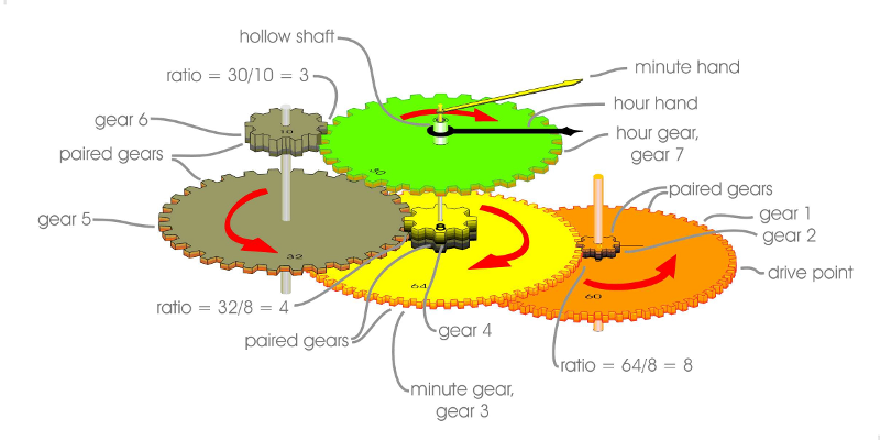
It is common in clocks to place both the minute hand and hour hand gears on the same shaft. The trick that is used to allow the two hands to turn at different rotational speeds is to make the hour hand shaft hollow, i.e. tubular as shown in Figure 9. Then the minute hand axle is passed up through the hollow hour shaft to independently turn the minute hand. Each shaft has its own separate drive gear on the far side of the clock face. In Figure 9, we see the orange gear driving the minute hand gear which is yellow. The minute hand gear's shaft goes up through the hollow hour hand's shaft and is free to turn at a different rate than the hour hand. The minute hand clips onto the protruding minute hand shaft.
 |
| Fig. 9. Gear arrangement in most clocks, those that use the same clock face for both minute and hour hands. These employ a hollow hour hand axle with the minute hand axle going up through the hollow hour hand axle. This way, both are free to turn independently. |
| previous:part 1 | up: home | next:part3 - conclusion |


