|
Figure 1. Some common conformal mappings as applied to images, fields, and a grid. The four mapping functions are shown in the horizontal set of buttons (they require pushing "transform" to activate). The first function, zn has a user adjustable n value (type in a new value between 0 and 2 in the n = box). The various images are shown as the vertical set of buttons on the right (give each image a little time to load).
This flash animation is intended to illustrate that conformal mapping is very much like morphing an image in photo shop, but in this case we morph one valid fluid flow or electric field pattern into another. This allows us to start with a very simple flow or electric field and from it to "graphically" obtain all sorts of other flow and electric field patterns. The initial coordinates, i.e. z-space or (x,y), are shown as a green grid and are warped by the transformations. The final coordinates, i.e. w-space or (u,v), are shown in light gray. Note that these are complex spaces, i.e.: To aid understanding, we show the transformation process as a series of small steps. Normally, this is done a single step. The transformations also require scaling factors, e.g. w = zn is really more like w = a(bz)n where a and b are real scaling factors.Conformal mappings use complex functions that are "analytic". One of their properties is that they are orthonormal. This means that even though a mapped grid is warped, the originally perpendicular grid lines will remain perpendicular at the intersection points. Another property is that if we map a field that satisfies Laplace's equation, such as simple fluid flow or magnetic fields, the mapped fields will also satisfy Laplace's equations and are therefore valid fields. We show the transformations w = zn, w = ez, w = sinz, w = z + 1/z. There are many more transformations, such as the rest of the complex trigonometric functions, complex hyperbolic functions, and polynomials in z. |
| Other postings by the author | |
| up: Conformal mapping contents | |
| next: Conformal mapping II | |
Conformal mapping to solve Laplace's Equation
Laplace's equation is a defining equation of electrostatics, low speed fluid flow, and gravitational fields. In two dimensions Laplace's Equation can be written as
where Φ is the potential as appropriate for the problem at hand. In the usual problem, we know the values of Φ on the boundaries of a particular region of space and we want to solve for Φ in the interior of that region. Conformal mapping is one of the standard methods for producing such a solution. For another solution method, i.e. separation of variables, see my postings on water waves.
The mappings
Conformal mapping makes use of a particular type of function of complex numbers called analytic functions. These functions map the points in the complex plane into a distorted second complex space. Figure 1 at the right demonstrates a few such mappings, where the complex planes shown there also include images to aid in the understanding of this mapping process. This mapping process is similar to the projections of the Earth's spherical surface onto a flat sheet of paper to make the standard maps of the world. (Histories of map projections are here and here.) What makes conformal mappings so useful is that they map a solution of Laplace's equation into another solution of Laplace's equation.
There are many complex analytic functions and each one defines a particular mapping (or distortion) of the complex plane as shown in Figure 1. Additional mappings can be found at Wikipedia, Wolfram, Mathews-Howell/Fullerton or Rotorbrain/Foote-interactive mapping, to name a few places.
Our first example
Below, in Fig. 2 we start with a very simple solution to Laplace's equation, a solution representing constant horizontal flow of a fluid above a flat plate. We then use various conformal mappings to distort this solution into other solutions of Laplace's equation, representing flow around various distortions of that plate. We see that our one simple starting solution can give rise to a whole family of solutions.
We go on to use conformal mapping to get algebraic solutions to all the various distorted solutions.
|
| |||||||

| Fig. 2a. Very simple, constant horizontal flow with the associated velocity potential shown.
The associated potential is given by the equation:
Φ = x (2.1) and results in a fluid velocity as given by: v = −∇Φ = −∂Φ/∂x ax − ∂Φ/∂y ay = −ax , (2.2) where ax and ay are the unit vectors in the x and y directions. (For an explanation of velocity potentials see my postings on water waves.) This flow pattern can be mapped into more complex geometries using conformal mapping as we show next. | ||||||

| Fig. 2b. This figure shows the result of applying the conformal transform,
w = z½ (2.3) to the solution shown in Fig. 2a. This transform is also shown in Figure 1, as applied to various images. The flow shown in Fig. 2b is that of fluid circulating around a corner made of rigid material. Because the original flow (that in Fig. 2a) satisfied Laplaces equation and because the transformation was conformal, we can be assured that the transformed flow will also satisfy Laplace's equation. It therefore will be the correct flow solution for irrotational, incompressible flow in a corner (see my earlier posting for a discussion of irrotational incompressible flow.) Basically the square root transform used here bends the x axis at the origin and rotates it by 90° as shown by the red arrow. The y axis is rotated by 45°. A detailed, more accurate mapping of this function is shown in a later posting. | ||||||
| |||||||

|
Fig. 2c. This figure shows the result of applying the conformal transform:
w = z2 (2.12) to the solution of Laplace's equation shown in Fig. 2a. This transform can also be shown in the animation in Fig. 1 if n in that animation is set to the value 2. The flow shown in Fig. 2.c is that of a fluid circulating around the end of a horizontal plate that lays along the positive x-axis. The flow starts in the upper right hand quadrant and flows in the negative x-direction until it passes the y-axis at which point it sweeps downward and to the right, exiting in the lower right hand quadrant. The transformation has rotated the negative x-axis in the counter-clockwise direction all the way so it coincides with the positive x-axis. This is indicated by the red curved arrow. The grid and flow potential have been warped consistent with this. A more accurate detailed mapping of the mapping is shown in a future posting. Using the animation in Fig. 1, you can play with the more general transformation
| ||||||
| |||||||
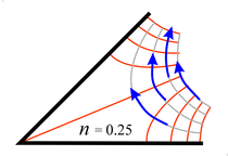
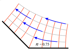
| Fig. 2d - A sample of other flow patterns from the zn transform | |||||||
| |||||||
More on incompressible, irrotational flow
Conformal mapping applies to incompressible, irrotational flow because this type of fluid flow obeys Laplace's equation. Conformal mapping will map one solution of Laplace's equation into another solution. Often we apply a series of conformal mappings to fit complex boundary conditions.
Fluids behave incompressibly and irrotationally if viscosity is not a significant force. Many commonly occurring air and water flow patterns can be approximated as incompressible and irrotational. The air flow around wings of an aircraft traveling considerably less than the speed of sound, fits this criteria, as does the flow around fan and windmill blades. The same is true of airflow around the front 60% of an aerodynamically clean automobile. A previous posting in this series dealt with water waves which involve incompressible, irrotational water flow having a gravitationally controlled free surface.

In the last series of images above we show some other flow patterns obtainable by the zn transform. Note that the last two simply involve starting with the whole space filled with flow, instead of only the upper half space as shown in Fig. 1. Also note that the bending point of the x-axis can be moved by using the (z − x1)n transform in place of zn, where x1 is the point on the x-axis where the bend is to occur.
Copyright, P. Ceperley, September 2010.
| Other postings by author | up: Conformal mapping contents | next: Conformal mapping II |


